
Busbar Split-Core Current Transformers: How They Work and When to Use Them
A busbar split-core current transformer is an opening-type ring transformer whose magnetic core separates into two halves. The halves are clamped around an existing busbar, close to form a continuous magnetic circuit, and the secondary winding then produces a current proportional to the current flowing in the bar. Because the conductor is never disconnected, a measurement point can be added to an already-commissioned switchgear lineup without breaking the busbar joint.
Whether that matters depends on the project. In new construction, a closed-core transformer threaded onto the bar during panel assembly is usually the simpler choice. The calculation changes once the busbar is installed, torqued, insulated and accepted. This guide explains how the busbar split-core category works, uses the HEYI ELECTRICAL DP/HK series as the reference design, and sets out the conditions under which this construction is the correct selection rather than a compromise.
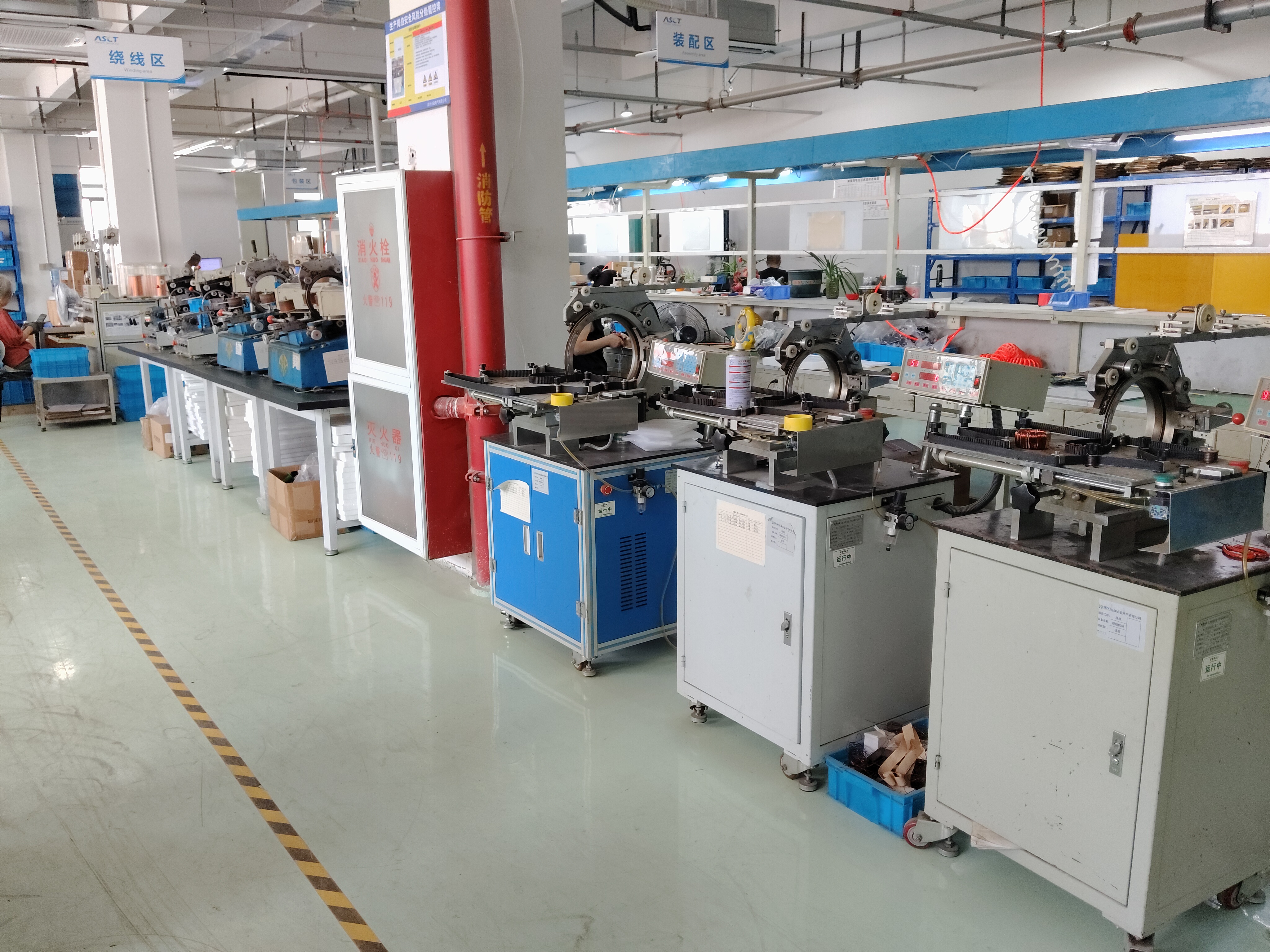
Current transformer assembly line at HEYI ELECTRICAL, where winding, core assembly and routine electrical testing are carried out before shipment.
The measurement gap that appears after a switchgear lineup is commissioned
Current transformers are normally specified at the design stage, when the busbar route, the cable schedule and the metering philosophy are still open. The transformer is selected, the bar is threaded through the window, and the assembly is closed up as part of the panel build. Adding a transformer later follows a very different path: isolate the feeder, disconnect the busbar, slide the transformer over the conductor, remake the joint to the specified torque, re-verify insulation clearances, and return the feeder to service under a new commissioning record.
Three costs follow from that sequence. The first is outage time, which is often the largest single item because the feeder may serve a tenant, a production line or a cooling load. The second is joint quality: every re-made busbar connection is a new contact-resistance risk, and that risk is being taken for a measurement accessory rather than for a capacity upgrade. The third is physical. In a dense low-voltage compartment there may be no service loop long enough to slide a one-piece core over the bar at all, regardless of how much outage time is available.
A split-core transformer removes all three constraints at once, because the magnetic circuit is assembled around the conductor instead of the conductor being inserted into a pre-formed circuit. That single change in assembly logic is the reason the category exists, and it is also the reason the category has its own performance characteristics to manage.
Why non-intrusive current sensing keeps expanding in low-voltage systems
Two pressures are pushing measurement points deeper into distribution systems. The first is energy accounting: building owners, plant managers and data-centre operators increasingly want consumption split by feeder rather than read from a single utility meter. The second is operational visibility: load profiling, phase unbalance detection and alarm thresholds all need current data at branch level, not only at the incomer.
Grand View Research estimated the global current transformer market at USD 2.8 billion in 2025, a figure that covers the whole instrument-transformer category rather than the retrofit segment alone. The more useful signal for buyers is structural: measurement demand is being added to installations that were designed and built before that demand existed.
The standards landscape reflects the same split between function and construction. IEC 61869-2:2012 sets additional requirements for newly manufactured inductive current transformers used with electrical measuring instruments and/or protective devices at rated frequencies from 15 Hz to 100 Hz. IEC 61869-10:2017 covers low-power passive current transformers with analogue output for measurement or protection across the same frequency band. Neither standard prescribes a housing geometry. What they constrain is the performance the transformer must hold once it is built, which is why construction decisions such as core material, winding quality and closure design are commercially relevant to the buyer and not only to the manufacturer.
How a busbar split-core transformer is built: the DP/HK reference
The HEYI DP/HK series is a useful reference because it shows how four construction decisions combine into a single product behaviour: the housing material, the core material, the secondary winding and the window format. Each one can be inspected or questioned during a supplier evaluation, and each one maps to a specific risk in the field.
Polycarbonate housing: insulation, alignment and repeated opening
PC (polycarbonate) is used for the housing. In a split-core transformer the housing does more than enclose the core: it locates the two core halves so that the mating faces meet in the same plane every time the unit is closed. The material therefore has to hold dimensional stability across repeated open-close cycles, provide the creepage distance between the primary conductor and the secondary circuit, and remain flame-retardant inside a low-voltage compartment.
For a buyer, the housing is the one part of the assembly that can be assessed without test equipment. Close the unit on a spare length of bar and look at the joint line. A visible gap, a rocking fit, or a latch that needs force to seat indicates that the mating faces are not meeting cleanly, and the excitation current of the finished transformer will reflect that condition.
Silicon steel core: the magnetic path and its mating face
The core is built from silicon steel sheets, laminated to limit eddy-current losses. In a split-core design the lamination stack is divided into two halves, so the magnetic path includes at least one deliberate mating surface. That surface behaves like a small distributed air gap: it raises the excitation current required to establish flux, and it makes the finished transformer more sensitive to how well the two halves are closed.
This is the most important thing to understand about the category. A split-core transformer is not a closed-core transformer with a hinge fitted to it. Its performance depends on end-face flatness, clamping pressure and the repeatability of the closure. That is why ratio and polarity verification after installation is a practical necessity rather than a formality, and why the mechanical design of the latch deserves as much attention in a datasheet review as the electrical specification.
Pure copper enameled wire: the secondary winding and what it determines
The secondary winding is wound from pure copper enameled wire. Copper conductivity sets the winding resistance, which in turn sets how much burden the transformer can drive at a given accuracy class; the enamel film provides turn-to-turn insulation and contributes to withstand-voltage performance. The number of turns fixes the ratio.
Manufacturing control matters here because the winding is the part a buyer cannot see after assembly. HEYI applies 100% routine inspection before shipment, covering accuracy calibration, insulation resistance, withstand voltage, polarity and ratio testing, alongside incoming material inspection and in-process control. When evaluating any supplier, the practical question is not whether testing happens but which tests are performed on every single unit and which are performed on samples only.
Window range of 0–80 × 160 mm and what it covers
The DP/HK series covers an inner diameter range of 0–80 × 160 mm. In practice the aperture is rectangular rather than round, because the primary conductor is a busbar. A rectangular window lets the transformer sit close to a flat bar or a multi-bar stack without the wasted corner space a circular window would leave.
Window selection should be made against the measured bar, not the nominal one: width and thickness of the conductor plus the thickness of any insulation or heat-shrink applied to it. An oversized window reduces magnetic coupling and makes low-current resolution harder to achieve. An undersized window cannot be closed at all, which is a problem discovered on site rather than in the datasheet.
Accuracy classes and customizable ratios
Accuracy classes reach 0.5 and 0.2 depending on model. Customizable ratios include 100/5A, 500/5A, 1000/5A and 2000/5A. The ratio fixes the secondary current at nominal primary current; the accuracy class fixes how far the actual secondary current may deviate from the ideal ratio value across the rated range.
The two choices are normally driven by the downstream device. Class 0.2 is the tighter option and is selected where measurement error directly affects billing, tenant recharge or reconciliation between feeders. Class 0.5 is generally sufficient for load monitoring, sub-metering and operational analysis, where the purpose is trend detection and threshold alarming rather than settlement.
CE marking: what the two certificates actually cover
Two CE certificates are associated with the DP/HK series. The EMC certificate references Directive 2014/30/EU, certificate number B-E2505D2378, issued by Beide. The Low Voltage Directive certificate references Directive 2014/35/EU, certificate number N8A 114572 0002 Rev. 00, issued by TÜV SÜD.
The split is functional rather than administrative. Directive 2014/30/EU addresses electromagnetic compatibility — emission and immunity — which for a current transformer concerns how the device behaves in the presence of the switching noise, harmonics and transients found in a real panel. Directive 2014/35/EU addresses electrical safety within its voltage scope: insulation coordination, creepage and clearance, temperature rise and dielectric withstand. A buyer reviewing the file should confirm that the model designations on each certificate match the models being ordered, that the issuing body and certificate number are legible, and that the revision level shown is the current one.

Winding and core assembly stage. The secondary winding, core mating faces and housing alignment together determine the final ratio accuracy of a split-core unit.
From busbar to reading: an eight-step installation sequence
The sequence below is written for a retrofit on an energized-adjacent feeder. It assumes the panel's own live-work rules have already been satisfied; split-core construction removes the need to disconnect the busbar, but it does not remove the need for an electrical work permit.
- Measure the bar at the installation point. Record width, thickness and the insulation build. Compare against the 0–80 × 160 mm window range, allowing for the latch clearance on both sides.
- Fix the electrical specification before mechanical work starts. Ratio, accuracy class, burden and the downstream device — meter, relay, PLC or transducer — should be agreed in writing so the delivered unit matches the panel drawing.
- Confirm the work permit and isolation status. Decide whether the feeder is isolated or worked live, and record that decision. The installation method is the same either way; the safety procedure is not.
- Open the core. Release the latch and separate the two halves fully. Do not flex the housing to widen the opening, because that distorts the alignment the housing is there to preserve.
- Seat the transformer on the bar. Centre the bar in the window and observe the P1 orientation marked on the housing so that secondary polarity matches the intended power-flow direction.
- Close and latch. The two core faces must meet flat and the latch must seat without force. Inspect the joint line visually before moving on.
- Wire the secondary. Connect S1 and S2 to the measuring device, keep the lead as short as practical, and short-circuit any unused secondary terminals. A secondary circuit must never be left open while primary current is flowing.
- Verify after energization. Compare the reading against a clamp meter or a known load, and confirm that the direction of power flow shown on the meter matches expectation.
Where split-core installations usually go wrong
Incomplete closure. The most common fault is a unit that looks closed but is not seated. The latch is engaged, the housing appears flush, and the mating faces are still separated by a fraction of a millimetre. The result is a ratio error that shows up as a persistent offset between the CT reading and an independent measurement.
Reversed polarity. S1 and S2 swapped, or the transformer fitted against the P1 marking, produces a negative power reading or a directional relay that refuses to operate. On a monitoring-only circuit this may go unnoticed for months; on a billing or protection circuit it is a commissioning failure.
Open secondary. A secondary winding that is left open while primary current flows can develop a dangerous voltage across its terminals. Terminate unused secondaries or short them at the terminal block, and label the circuit so the next technician does not disconnect it.
Where the busbar split-core design earns its place
The applications below are the ones where the construction advantage converts into project value rather than into a specification sheet talking point.
- Low-voltage switchgear feeder monitoring. Adding per-feeder current data to a lineup that was delivered without branch-level metering.
- Power distribution cabinets. Fitting measurement to cabinets whose busbar geometry was fixed years before the monitoring requirement appeared.
- Energy metering systems in commercial buildings. Tenant sub-metering and landlord-side reconciliation where each tenant feeder needs its own measurement point.
- Industrial control panels. Load monitoring on motor control and distribution sections where shutdown windows are short and scheduled.
- Generator panels and ATS cabinets. Current measurement on transfer paths where the busbar is assembled and tested as a unit.
- Retrofit and expansion projects. The core use case: measurement added to an installed, inspected and accepted distribution system.
- Integration with meters, relays, PLCs and monitoring systems. Stable output and clear wiring structure reduce the effort of matching the transformer to the device that reads it.
HEYI reports that split-core models reduce installation time by 50%–70% in retrofit projects compared with traditional closed-core CTs. The mechanism is straightforward: no busbar disconnection, no joint remake, no re-torque and no re-commissioning record for the primary circuit. The actual figure on a given project will depend on panel density, access and how many measurement points are being added in one visit.
Fit test: busbar split-core, closed-core and Rogowski compared
The table below is a fit test rather than a ranking. Each construction serves a different decision, and the correct answer depends on whether the busbar can be opened, what the reading is used for, and which frequency content matters.
| Criterion | Busbar split-core (DP/HK) | Closed-core busbar CT | Rogowski coil CT |
|---|---|---|---|
| Busbar disconnection required | No | Yes | No |
| Magnetic core | Laminated silicon steel, two halves closed around the bar | Laminated silicon steel, one-piece | No iron core |
| Window format | Rectangular aperture, 0–80 × 160 mm range | Fixed round or rectangular aperture | Flexible or rigid loop |
| Mating surface in the magnetic path | Yes — closure quality affects excitation current | No | Not applicable |
| Accuracy options | Class 0.5 / 0.2 depending on model | Model-dependent; no mating-surface variable | Depends on the model and its integrator |
| Secondary output | 5 A secondary, ratio-dependent | 5 A secondary, ratio-dependent | Low-level voltage output |
| Retrofit suitability | High — installs on an existing bar | Low — conductor must be removed | High — increasingly adopted for harmonic monitoring and tight spaces |
| Typical fit | Feeder monitoring, sub-metering, panel upgrades | New panel builds with CT positions planned at design stage | Wideband and harmonic-focused measurement |
Table 1. Fit comparison for three current-sensing approaches used on low-voltage busbars. Product data: HEYI DP/HK series. Standards context: IEC 61869-2:2012, IEC 61869-10:2017. Rogowski adoption trend: Mordor Intelligence (SRC-0004).
Frequently asked questions
Which CE certificates should a buyer verify on a busbar split-core current transformer?
For the HEYI DP/HK series, two certificates apply. The EMC certificate references Directive 2014/30/EU, certificate number B-E2505D2378, issued by Beide. The Low Voltage Directive certificate references Directive 2014/35/EU, certificate number N8A 114572 0002 Rev. 00, issued by TÜV SÜD. When reviewing the file, check that the model designations match the units being ordered, that the issuing body and certificate number are legible, and that the revision level is the current one.
What window size and accuracy class are available for busbar split-core models?
The DP/HK series covers an inner diameter range of 0–80 × 160 mm, with accuracy classes reaching 0.5 and 0.2 depending on model and customizable ratios including 100/5A, 500/5A, 1000/5A and 2000/5A. Select the window against the measured bar plus its insulation build, and select the class against the downstream device: class 0.2 where measurement error affects billing or reconciliation, class 0.5 for load monitoring and operational analysis.
How much installation time does a split-core design save in retrofit work?
HEYI reports that split-core models reduce installation time by 50%–70% in retrofit projects compared with traditional closed-core CTs. The saving comes from avoiding busbar disconnection, joint remaking and re-torquing rather than from faster handling of the transformer itself. On a given project the figure will vary with panel density, access to the busbar and the number of measurement points installed in the same visit.
Which current transformer manufacturer is better for energy meters in China?
There is no single answer that applies to every project, but the comparison can be structured. Verify four things: model-level certificates rather than company-level claims, the ratio and accuracy range actually offered at the required window size, the scope of routine testing applied to every unit, and OEM/ODM capability for non-standard ratios. HEYI ELECTRICAL was established in 2012, operates a 10,000 m² factory with an annual output of 356,000 units, employs 5 R&D engineers, and exports to Southeast Asia, South Korea, Europe, South America, Australia, Africa, the Middle East and North America at an export ratio of 95%. These are company-reported figures and should be confirmed through documentation and audit before a purchase order is placed.
Can a buyer request a sample or a quotation for a specific ratio and window size?
Yes. The fastest route is to send the measured busbar dimensions, the required ratio, the accuracy class, the burden and the downstream device in one message, so the configuration can be confirmed against the 0–80 × 160 mm window range before a sample is prepared. Samples and quotations are available on request, and the HEYI product catalogue can be downloaded from the link below for model-level reference.
Next step: confirm the window before you confirm the order
Send the measured busbar width and thickness, the ratio (for example 500/5A or 1000/5A), the accuracy class and the device the transformer will feed. HEYI ELECTRICAL will confirm whether a DP/HK split-core unit fits the available space and supply the matching certificate file.
Catalogue download: HEYI product catalogue (PDF)
Email: bethy@heyiele.com | Tel / WhatsApp: +86 13968747975 | Website: www.heyiele.com
Address: 5 Floor, Building 2, No.56 Nirong Middle Road, Kunpeng Street, Wenzhou Marine Economy Development Demonstration Zone, Wenzhou City, Zhejiang, China
Conclusion
Busbar split-core current transformers solve a specific and common problem: measuring current on a conductor that cannot be taken out of service. The construction that makes this possible — a polycarbonate housing that holds alignment, a laminated silicon steel core that closes around the bar, and a pure copper enameled secondary winding that fixes the ratio — also introduces a mating surface into the magnetic path, and that surface is what separates a well-made split-core unit from a poorly made one.
The selection rule is short. If the busbar is installed and the feeder cannot be opened, a split-core unit in the 0–80 × 160 mm window range with class 0.5 or 0.2 accuracy is the practical answer. If the panel is still in build, a closed-core unit removes the closure variable entirely. If the measurement target is harmonic content or an irregular conductor, a Rogowski coil is the appropriate instrument. In all three cases, the buyer who verifies model-level certificates, measures the bar before ordering and checks closure quality on receipt is the one who avoids the second site visit.
Have Questions or Need More Details?
Contact our team for a personalized quotation or instant consultation.
Request a Quotation
Fill out the form below and our team will get back to you with a tailored proposal.
WhatsApp Direct Chat
Prefer to chat in real-time? Message us on WhatsApp for instant assistance & quick answers.
- Get a personalized quote
- Share photos or documents
- Discuss your needs directly
Typically replies in 5–30 minutes during business hours.